My goal is to get an example running with FreeRTOS and threads that manages a general BLE throughput to an app in the background. To build the app, I'm using React-Native, the javascript based development environment that can cross-compile. Let's jump right in!
Running an Example on the STM32WB Nucleo Board
STM32WBCubeIDE and STM32CubeProgrammer are the required/useful software from STM's website. This section falls into four parts: (1) set up the toolchain so you can talk to to the nucleo board, (2) flash the Bluetooth firmware, (3) ensure we can run a BLE pre-compiled example, and (4) import an STM32 example into CubeMX and run a BLE example.
Toolchain Setup
Step 1 is to download STM32CubeIDE and STM32CubeProgrammer – I had previously had a lot of issues running this natively on Mac, but it seems like version 1.3.0 works great natively (Windows support has always been good). To set up CubeProgrammer, you may have to download the Java JDK (one with JavaFX, aka version 8– if you've installed a more recent one [ java -version in terminal to check] you can simply delete the folder from /Library/Java/JavaVirtualmachines). This can be installed with brew on Mac OSX:
#if you don't have brew, get it with this command
/usr/bin/ruby -e "$(curl -fsSL https://raw.githubusercontent.com/Homebrew/install/master/install)"
brew update

brew tap AdoptOpenJDK/openjdk
brew cask install adoptopenjdk8
You also may actually have to show the Package Contents and click on the setup executable manually. You'll also need the ST-Link driver, installed with homebrew: brew install stlink.

The Cube Programmer interface is a new tool, and it's actually incredibly useful for checking/setting fuses, downloading firmware and programs, and reading/writing memory. It also works over the ST-Link, SWD, and DFU interfaces, so it's a great one-stop-shop for interfacing with the STM32.
The easiest first step is to connect your USB to the STM32 Nucleo board ST_LINK port (closer to the side/header). Of course, the Nucleo board has 2 STM32s on it– the main WB chip we'll be talking about the rest of the time, and a secondary STM32 chip that serves as an ST-LINK device for programming the WB. The programmer chip firmware should be updated first.
When you connect the STM32, you should see some flashing LEDs and a new device should appear in your Finder/File Explorer window. If we open the STM32 CubeProgrammer, we should see a Serial number if we refresh the right sidebar with 'ST-LINK' selected at the very top. Let's click Firmware Upgrade (again on the right) to update the included programmer on the Nucleo Board.
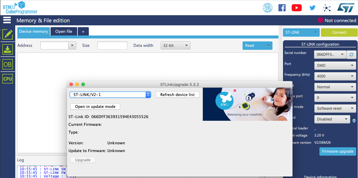
You'll have to click 'Open in Update Mode' and the 'Upgrade' to actually update the programmer.
Flashing the Wireless Co-processor Firmware
This is a two step process– we need to upgrade the underlying firmware on the coprocessor first and then flash the wireless stack we want to use (BLE in this case).
First, we should download the firmware pack from github. Within it we find the binaries for the wireless co-process in:
STM32CubeWB/Projects/STM32WB_Copro_Wireless_Binaries/STM32WB5x
You'll also find Release Notes.html in that folder, which gives us the memory addresses we need to use for each binary in a table towards the bottom called Firmware Upgrade Services Binary Table for our first step and Wireless Coprocessor Binary Table for our second step. We can see from this table that for the Nucleo, which is designed around the STM32WB55RG, the FUS firmware belongs at location 0x080EC000 and the stm32wb5x_BLE_Stack_full_fw should be flashed to 0x080CB000.
Option 1 (preferred): Use ST-Link
On the Nucleo board, you should be able to flash the firmware using the ST-Link. Given the same setup in STM32CubeProgrammer as above, you should be able to connect to the board simply by clicking the big green 'Connect' button. Make sure it's in Normal/Software Reset mode– you may need to hold down the Reset button on the board, hit Connect in the software, and immediately release the Reset button to get it to work.
Option 2: Use DFU mode
If the above is giving you any trouble, we can also program the board in DFU mode. We have to set up the jumpers on board to enable DFU mode by moving JP1 to USB_MCU and connecting pins 5 and 7 on CN7 (as shown here). We need to make sure we have the proper DFU drivers installed; on OSX, brew install dfu-util should do it; on Windows, the DFU drivers should be installed in C:\Program Files (x86)\STMicroelectronics\STM32Cube\STM32CubeProgrammer\Drivers\DFU_Driver, where you can click on STM32Bootloader.bat. It's also possible to get Windows DFU drivers from STM directly. Now If you plug it in to your computer from the USB_USER port, it should appear as a DFU device on your system and be accessible under the USB tab within CubeProgrammer. On Windows, the final thing worth considering if none of this is working is zadig libusbK conversion of existing drivers.
This has worked for me with Windows– I haven't tested in on OSX yet. People report (including myself) difficulty re-connecting over DFU once a firmware is flashed, so hopefully option 1 is working for you. If you really need DFU, some people have reported success by wiping the memory using the ST-Link and CubeProgrammer (use the Erasing and Programming screen and click Erase Selected Sectors after selecting all). You could also toggle the RDP bit under "OB" option bites (to 0xBB and then 0xAA), which will clear some bits of memory (make sure PCROP_RDP is checked under PCROP Options).
For custom boards, to get into DFU mode simply requires BOOT0 gets pulled to VDD(3.3), and the USB socket to connect GND to GND, D- to PA11, and D+ to PA12.
Now that we are ideally connected to the chip using CubeProgrammer (either over the ST-Link or over DFU), we can go ahead and flash the firmware.
We're first going to delete the existing firmware. As of this post, there are three firmware versions (0.5.3, 1.0.2, and 1.1.0) and they must be upgraded in order (you can't jump to 1.1.0 from 0.5.3 without install 1.0.2)– our next step will be to upgrade firmware versions in order. Finally, we'll flash the BLE firmware.
We can get to the Firmware Upgrade Service (FUS) by clicking the wifi-looking icon on the left menu; first click 'delete firmware'. After that operation completes, we'll flash FW 1.0.2 to address 0x080EC000:

You'll probably see a lot of FUS_STATE_IMG_NOT_AUTHENTIC warnings– I certainly have while going through these processes. This could mean you're trying to upgrade the firmware to an image that isn't allowed from the current firmware (like 'upgrading' to the same image, or skipping firmware version 1.0.2) or that something is going wrong with the upgrade process. Try it a couple times if you get this warning; if it persists, file it away and go on to the next step. If that fails too you can come back to this.
We can then try and upgrade again to the latest version of the firmware, at the same memory address:
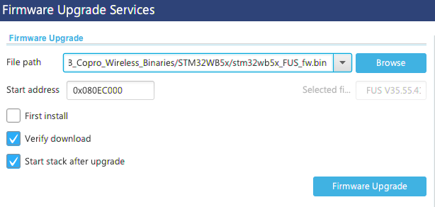
Finally, we install the BLE full stack at 0x080CB000 with 'first install' checked, repeating the process above.
As a note, it is also possible to do this from the command line with the tools installed alongside CubeProgrammer.
For windows, we need to add C:\Program Files (x86)\STMicroelectronics\STM32Cube\STM32CubeProgrammer\bin to our path; the way to do this is to search for 'env' from the windows toolbar, click 'Environmental Variables', click path in the first dialog, and add the above folder.
For OSX we can add the path of our application /Applications/STMicroelectronics/STM32Cube/STM32CubeProgrammer/STM32CubeProgrammer.app/Contents/MacOs/bin using a typical export command:
export PATH=$PATH:/Applications/STMicroelectronics/STM32Cube/STM32CubeProgrammer/STM32CubeProgrammer.app/Contents/MacOs/binThe command STM32_Programmer_CLI in OSX terminal or STM32_Programmer_CLI.exe in Windows cmd should both work; the port is specified as port=usb1 for DFU connected devices, or port=/dev/tty.usbmodem<XXXX> for OSX and port=COM<X> for Windows over ST-Link.
Some example commands that have worked for me to flash the firmware over DFU in Windows are shown here:
# first, move to the folder with the coprocessor binaries

STM32_Programmer_CLI.exe -c port=usb1 -fwdelete
STM32_Programmer_CLI.exe -c port=usb1 -r32 0x20030030 1


# IF the above says 00050300 it's at FUSv0.5.3. This MUST be first updated to v1.0.2 for any STM32WB5xx before you can update further (the latest is 1.1.0).  This is our prototype command: STM32_Programmer_CLI.exe -c port=usb1 -fwupgrade[FUS_Binary] [Install@] firstinstall=0, where Release Notes gives us Install@ parameter depending of the binary.  For STM32WB5xxG, as with Nucleo, this is:

STM32_Programmer_CLI.exe -c port=usb1 -fwupgrade stm32wb5x_FUS_fw_1_0_2.bin 0x080EC000 firstinstall=0


#now if we run the above command again we should see a new firmware version:

STM32_Programmer_CLI.exe -c port=usb1 -r32 0x20030030 1


Now I'm going to upgrade it again to the latest firmware (note difference in binary name):

STM32_Programmer_CLI.exe -c port=usb1 -fwupgrade stm32wb5x_FUS_fw.bin 0x080EC000 firstinstall=0

# This gives 'firmware not authentic error', no matter how I try to do the upgrade.  We're fine with just 1.0.2 though, so we'll ignore this issue.  Now we'll update the actual binary with the full BLE stack:

STM32_Programmer_CLI.exe -c port=usb1 -fwupgrade stm32wb5x_BLE_Stack_full_fw.bin 0x080CB000 firstinstall=0
NOTE: If your Nucleo board is giving you a 'no device found on target' error, make sure it is in 'Normal'/'Software Reset' mode, HOLD DOWN the reset button, initiate the programming, and THEN release the reset button once the ST-Link connection is 'WAITING FOR DEBUGGER CONNECTION'.
Download and Run a Pre-compiled Example
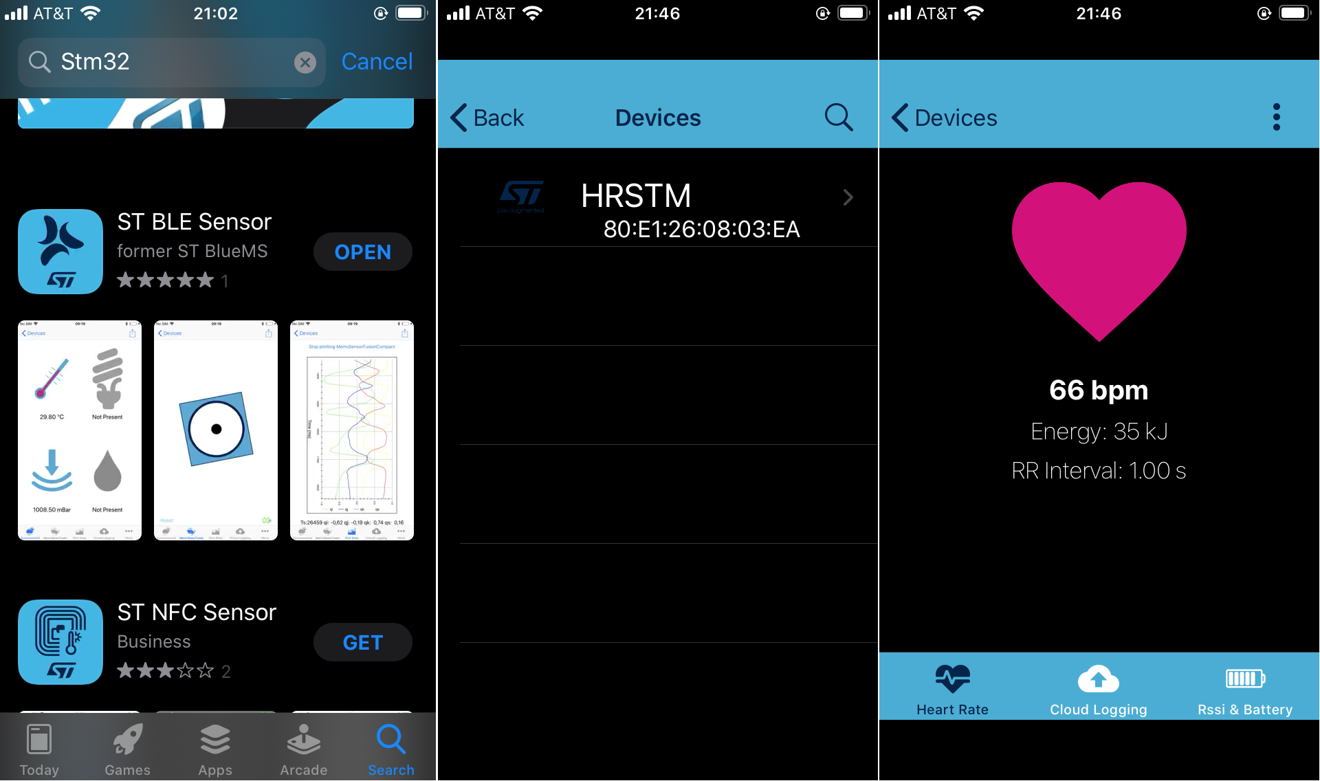
To make sure the BLE example is working properly out of the box, it's best to use the BLE_HeartRate binary and flash it directly to the board, and check it using the STM32 app downloaded from the iOS store.
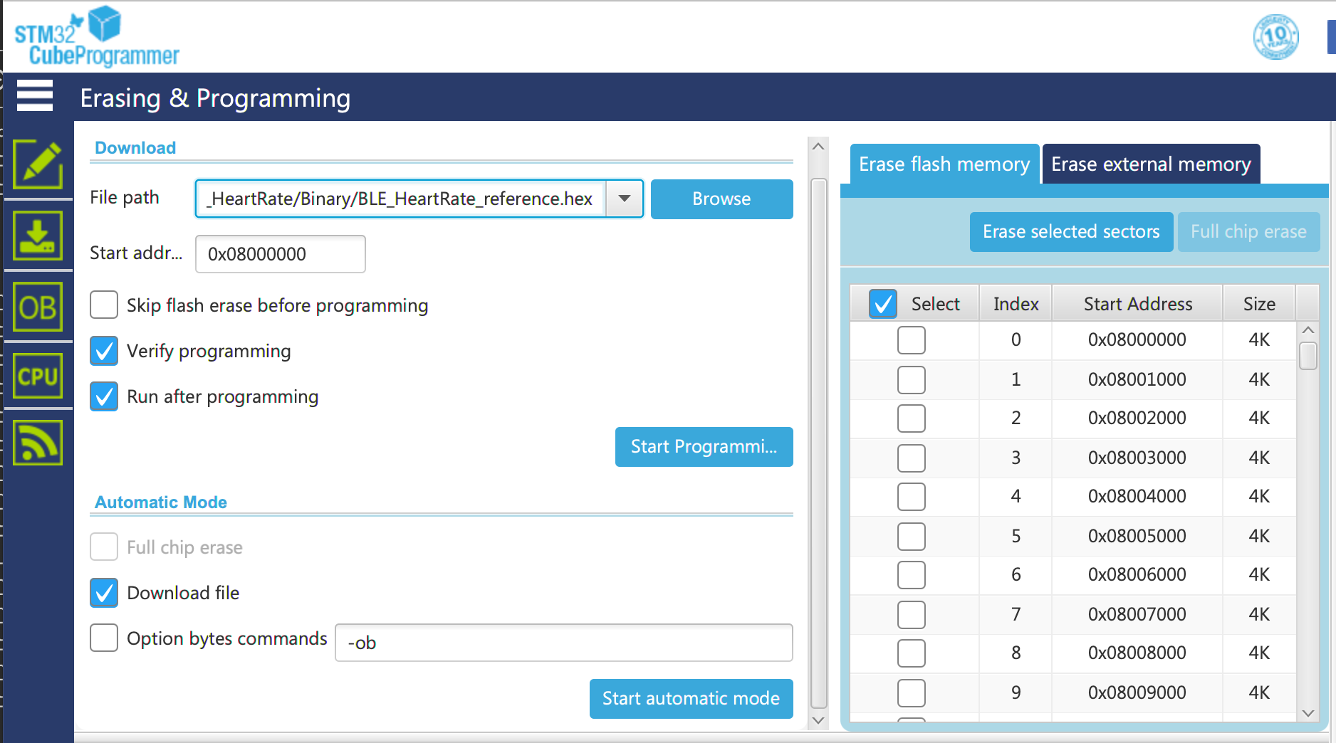
We can again use Cube Programmer with /Projects/P-NUCLEO-WB55.Nucleo/Applications/BLE/BLE_HeartRate/Binary/BLE_HeartRate_reference.hex from the second tab, 'Erasing and Programming'. Simply pick the file, enter a start address of 0x08000000, and click 'Start Programming'.
Now we install the iOS App 'ST BLE Sensor App':
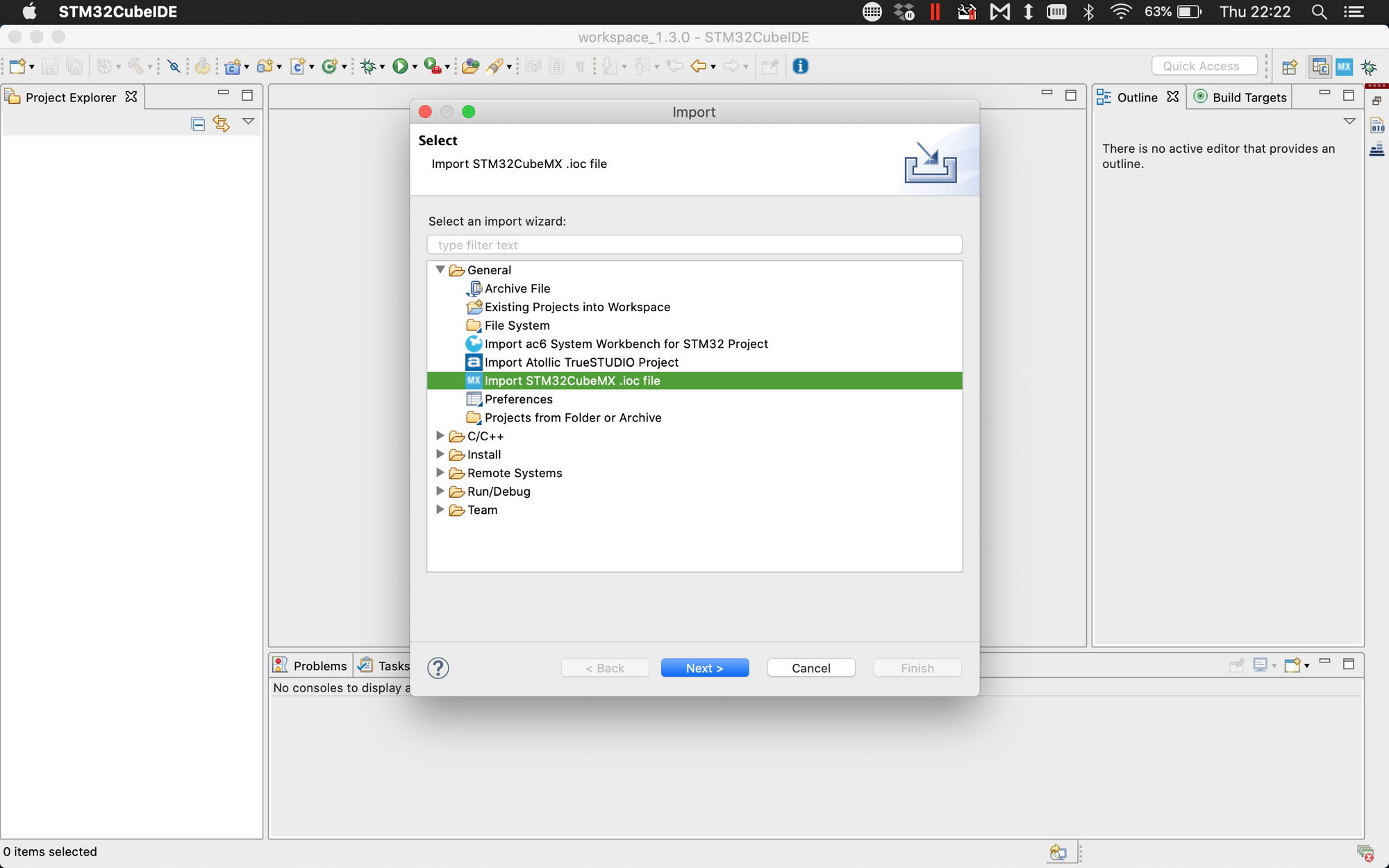
Download and Run an Example from CubeIDE
Now that we know we have the working BLE firmware and working code, and a way to test the STM32 example, let's try to import an example into CubeIDE where we can edit the C code and then download it to the Nucleo, and see if we get the same results.
For this example, we'll use the same BLE_HeartRate project, except now it will be the uncompiled C code we can then edit.
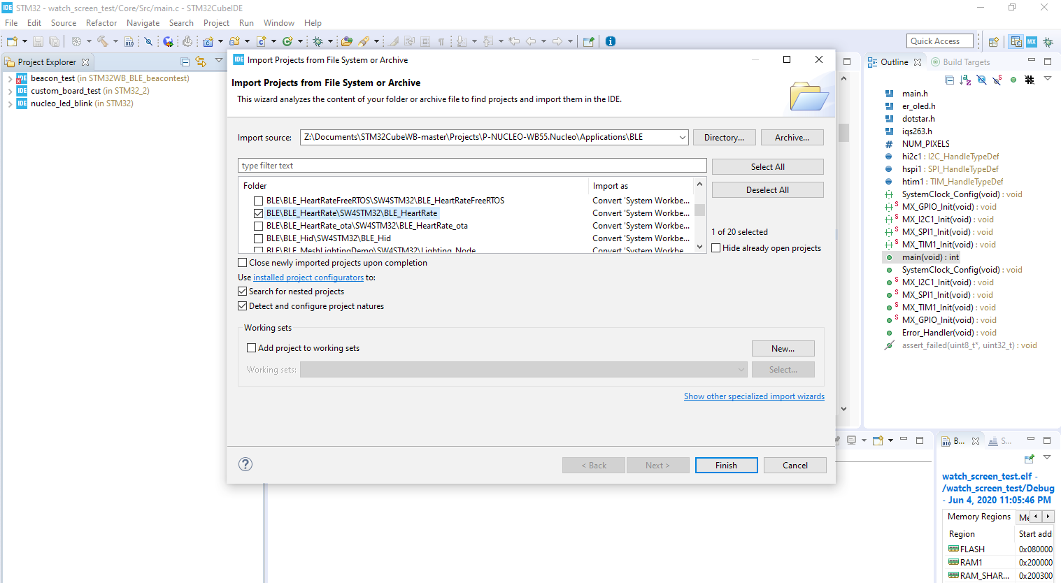
Select File->Open Projects from File System, then hit the directory button and select the Projects\P-NUCLEO-WB55.Nucleo\Applications\BLE folder. Click Deselect All, and then choose BLE\BLE_HeartRate\STM32\BLE_HeartRate, which is a System Workbench project.
If you hit 'okay' through the next few dialogs, you should have a project that will build and debug, connecting once again to the app! Make sure that your Nucleo board connects, that you can't see the HRSTM, and that it appears once you 'continue' the debug after programming.
Honestly, the OSX version of things doesn't work easily for this, and I'm not sure why– I get hard faults when I attempt to build/debug. Mac support has slowly been improving, but for this I'd recommend virtualizing Windows instead with CubeIDE.
There are a surprising number of ways to get hung up at this step, and imported projects aren't structured as nicely as CubeIDE-native IOC-based projects. There also appear to be some limitations with using BLE and FreeRTOS at the same time if you stick with the standard toolchain CubeMX and CubeIDE toolchain.
Creating an Example App that Receives BLE from the STM32
React-Native makes things nice and easy to develop across platforms. Expo is an environment that will let you write and hot-reload code from your browser and push changes to the app store; it's a really great tool.
Unfortunately Expo doesn't support BLE. Also unfortunately, you can't test your code in the iphone simulator included in XCode; they don't have support for interfacing with bluetooth on your Apple computer. That means we need to do our testing live on a real iPhone, and we need a developer account to push things to a real phone.
To do this we need a developer account, XCode, react-native, and polidea's ble plx react native library.
Install the Tools
Install Xcode from the App Store (or older versions from here if the latest version isn't compatible with your OS version and you don't want to upgrade.)
From a terminal install xcode command line tools with xcode-select --install. You also have to accept the xcode license with sudo xcodebuild -license. You should also set up a developer account; with Xcode open, click Xcode -> Preferences. Go to the Accounts tab, and add your developer account (which you might have to register for if you don't have one). Click manage certificates and add one using the add button at the bottom– this will give you a certificate for this computer.
Now we need watchman, flow, nvm, and the react native command line interface:
brew install watchman nvm flow
echo "source $(brew  --prefix nvm)/nvm.sh" >> ~/.bash_profile
source ~/.bash_profile
nvm install node && nvm alias default node
npm install -g react-native-cli
Set up the Project
#create a project
npx react-native init ReactNativeBLETest
#(install cocoapods with Homebrew if prompted)
#add the ble pod and generate
cd ReactNativeBLETest
npm install --save react-native-ble-plx
sudo xcode-select --switch /Applications/Xcode.app
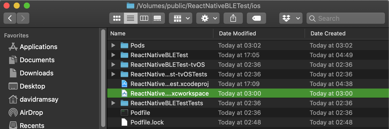
cd ios && pod installNow we can open this is Xcode– click on the .xcworkspace file to open it, NOT on the xcodeproj file (it won't build and you'll receive a cocoapod modulemap not found error otherwise)!
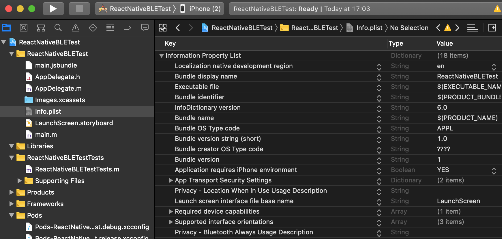
Open the main project folder and the Info.plist; right click in the area under the rows, click Add Row, and then scroll down to find 'Privacy– Bluetooth Always Usage Description'. No need to fill in the description string.
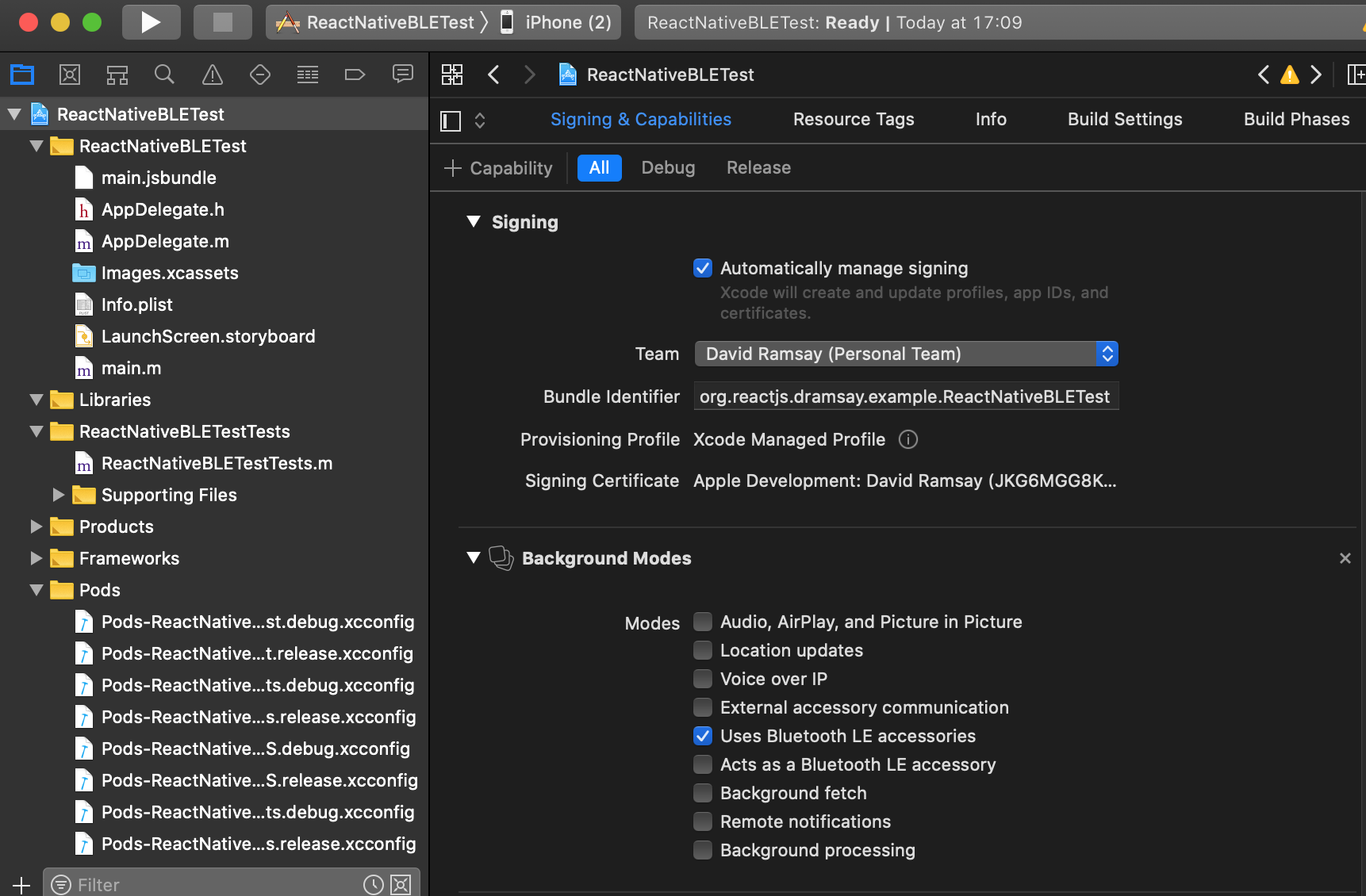
Next we select the high level project (the one with the blue icon in the left project explorer) and click Signing and Capabilities. Here we select our developer account from the dropdown menu (so we can sign it and test on our phone), and we also click the '+ Capability' button along the top, and select background modes to reveal an additional menu. From this menu we can select 'Uses BLE accessories' as seen below:
Now we'll set our target to our actual iPhone. Plug in the phone with a cable to the computer, and in the main Xcode menu select Product -> Destination -> iPhone (under Device). You should also be able to select it from the top bar of Xcode.
Make sure your iPhone is connected to the same WIFI network as your computer. Now let's hit the play button and see if it builds and loads onto our phone!
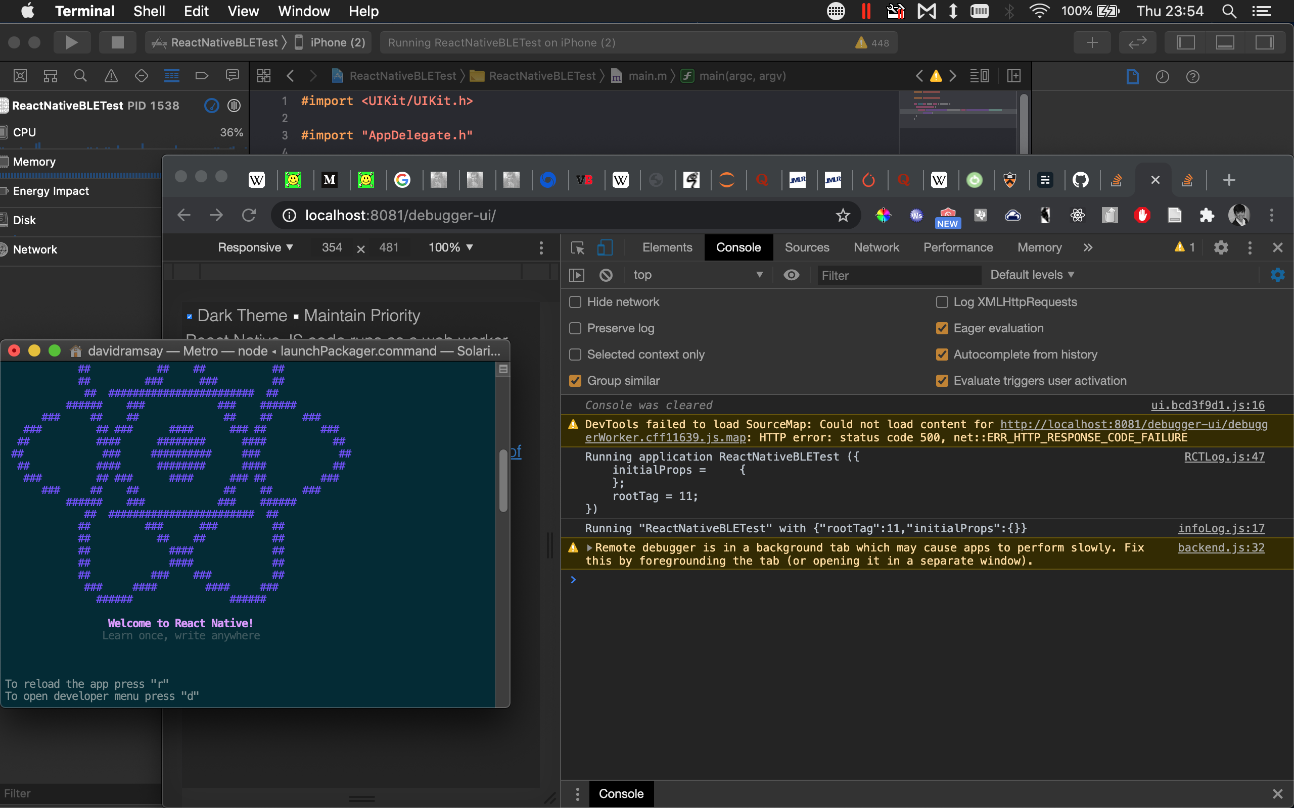
What should happen is that a terminal opens with the React logo. At the same time, to start debugging, you should open a Chrome/Firefox window, navigate to localhost:8081/debugger-ui/, and open the developer tools console with cmd+option+I. After you wait a minute or two, the example app should appear on your phone. Shake it, and hit 'Debug'. We should be able to reload the app (again from the Shake menu) after refreshing the debugger site and see the same logging in our browser console that we see below.
Troubleshooting: if you get a modulemap error, you probably didn't open the project from the .xcworkspace file. Do that instead.
If you get a 'Could Not Locate Device Support Files' error, you have an old iPhone like me. You'll need to git clone https://github.com/iGhibli/iOS-DeviceSupport.git and then enter the folder and run .sudo ./deploy.py and restart Xcode.
Add and Test BLE Functionality
We'll start by verifying we can accept data over BLE from the heart rate example we already have running on the Nucleo board. First, double check that you can still see the nucleo board as HRSTM within the official STM32 app.
In our main, top-level project directory, we'll add a BLE.js file alongside the App.js. Within BLE.js we'll add this basic code:
//BLE.js

import React, { Component }  from 'react';
import {
  View,
  Text,
} from 'react-native';

import { BleManager } from "react-native-ble-plx";

export default class BLE extends Component {

  constructor() {
    super()
    this.manager = new BleManager()
    this.state = {info: "", values: {}}
    this.ble_devices = {};
  }

  info(message) {
    this.setState({info: message})
  }

  error(message) {
    this.setState({info: "ERROR: " + message})
  }

  updateValue(key, value) {
    hexval = this.base64ToHex(value);
    console.log('update ' + key + ' : ' + hexval)
    this.setState({values: {...this.state.values, [key]: hexval}})
  }

  base64ToHex(str) {
    const raw = atob(str);
    let result = '';
    for (let i = 0; i < raw.length; i++) {
        const hex = raw.charCodeAt(i).toString(16);
        result += (hex.length === 2 ? hex : '0' + hex);
    }
    return result.toUpperCase();
  }

  componentDidMount() {
    if (Platform.OS === 'ios') {
      this.manager.onStateChange((state) => {
        if (state === 'PoweredOn') this.scanAndConnect()
      })
    } else {
      this.scanAndConnect()
    }
  }

  scanAndConnect() {
    this.manager.startDeviceScan(null,
                                 null, (error, device) => {
      this.info("Scanning...")
      console.log(device)

      if (error) {
        this.error(error.message)
        return
      }

      this.ble_devices[device.id] = {
            'name': device.name,
            'rssi': device.rssi
      }

      if (device.name === 'HRSTM') {
        this.info("connecting to HRSTM")
        this.manager.stopDeviceScan()
        device.connect()
          .then((device) => {
            this.info("Discovering services and characteristics")
            let r = device.discoverAllServicesAndCharacteristics()
            console.log(r)
            return r
          })
          .then((device) => {
            console.log('services')
            device.services()
              .then((services) => {
                  console.log(services)
                  console.log('characteristics')
                  for (s in services){
                      console.log(services[s])
              device.characteristicsForService(services[s].uuid).then((c)=> {
                          for (i in c){
                              console.log(c[i])
                              if (c[i].isNotifiable){
                                  console.log('registering notifiable!!')
             device.monitorCharacteristicForService(c[i].serviceUUID, c[i].uuid, (error, characteristic) => {
                                      if (error) {
                                        this.error(error.message)
                                        return
                                      }
                                      this.updateValue(characteristic.uuid, characteristic.value)
                                  });
                              }
                          }
                      })
                }
            })
          })
          .then(() => {
              this.info("Listening")
          }, (error) => {
              this.error(error.message)
              this.info(error.message)
          })
      }
    })
  }

  render() {
    return (
      <View>
        <Text>{this.state.info}</Text>
        {Object.keys(this.ble_devices).map((key) => {
            return <View key={key}>
                <Text style={{fontWeight:'bold',color:'red'}}>
                    {this.ble_devices[key]['name'] + ' : ' + this.ble_devices[key]['rssi']}
                </Text>
                <Text key={key}>
                {key}
                </Text>
                </View>
        })}

        {Object.keys(this.state.values).map((key) => {
          return <Text key={key}>
                   {"\n" + key + ": " + (this.state.values[key])}
                 </Text>
        })}
      </View>
    )
  }
};After creating this component, we can integrate them into the 'getting started' app by editing the App.js file in the top level directory. We first add a reference to our BLE component at the top of the file: import BLE from './BLE';. Secondly we add the BLE component to our main view in App.js– in the line just below the <Header /> we add <BLE />.
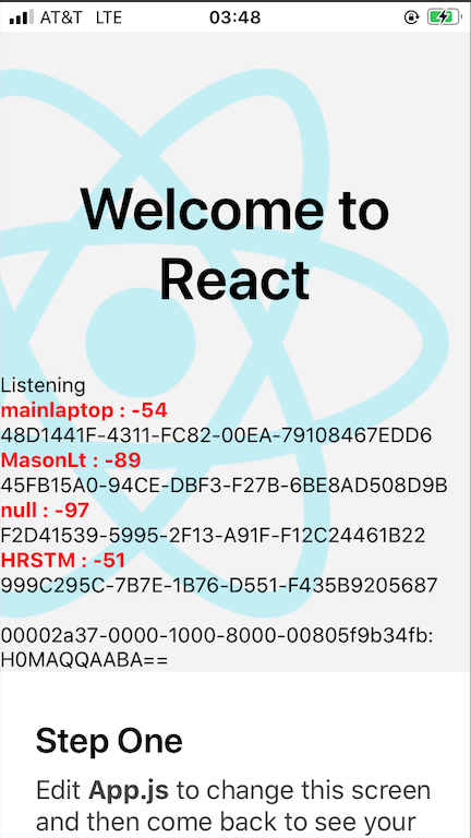
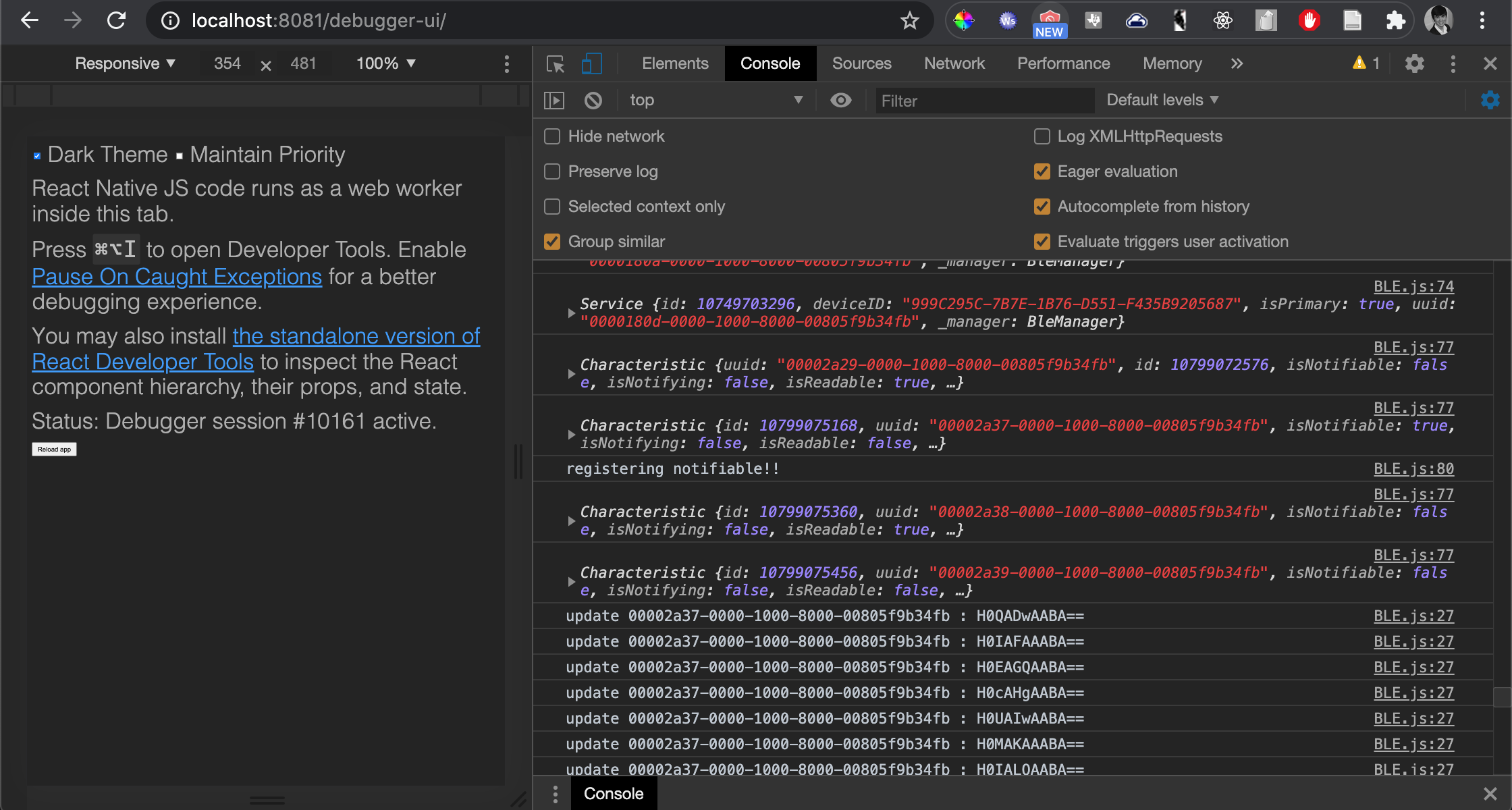
Now we'll go back to our app, shake, and click reload (or go to our react terminal and hit 'r'). And voila! BLE devices are scanned, HRSTM is connected to, its services and characteristics are enumerated, and it registers a streaming service to write data to the screen.
Digging Into Bluetooth
Let's review Bluetooth, and how the communication works on the STM32WB.
How Bluetooth Works
Bluetooth devices have a MAC address or similar, certified 12-digit hex address (commonly BD_ADDR). To talk over bluetooth, we have a discovery process, a negotiation, and then a connection in active (ongoing), sniff (interval), hold (predefined sleep), or park (sleep until master commands wake) modes. If devices are paired once, they will then be bonded and automatically establish a connection. The pairing process varies; it can just work, require PINs, codes etc.
Bluetooth works with one master and (potentially many) slaves.
Bluetooth devices implement different profiles. HID (human interface device) is a common one for input devices; SPP (Serial Port Profile) is good for replacing serial comms (data bursts), and there are others for audio (A2DP, APTX).
Bluetooth classes refer to range; 1=100m, 2=20m, and 3=5m.
We have Bluetooth 2.1 and 3, where the max basic speed is ~2.1Mbps (though 3 introduced a high speed mode capable of 24Mbps). Bluetooth 4 introduces the categories of Classic, High Speed (HS), and Low Energy or Smart (BLE). From now on I'll call Bluetooth Classic 'Bluetooth', as it really matches the previous 2.1/3 specs. HS is once again 24Mbps (This is actually more like WIFI on the physical layer– normally we think of bluetooth as a quickly changing frequency hopping carrier in the 2.4GHz band, but the 24Mbps uses a standard wide-band frequency division technique).
GAP
GAP (Generic Access Profile) is how a Bluetooth device advertises and connects. GAP defines the role for a device as central or peripheral, and controls the advertising data and scan response packets. Advertising packets are mandatory and sent out at intervals; scan responses are optional to provide a bit more information to scanning devices in the discovery phase. Both packets contain up to 31 bytes of data. Advertising intervals are on the order of tens of ms to seconds.
This advertising process is usually meant to establish connections, but it can be hijacked to simply advertise data to anyone around in the 31 byte payload– this is called Broadcasting in BLE. Advertising packets are structured as:
Preamble | Access Address | PDU | CRC | CTE
The preamble is 1 byte of alternating 0s and 1s, for synchronization.
The access address is a 6 byte value that is unique to that type ofadvertisement. For BLE, that address is always 0x8E89BED6.
the CRC is a 3 byte cyclic redundancy check (error detection), and the CTE is a small 16-160 us burst of a '1' value known as a continuous tone extension, sent 250 kHz above the main carrier frequency, to measure transmission path (IQ) quality.
The PDU, or protocol data packet is 2-258 bytes, and is broken down as follows:
Header | Payload
Where the Header is 16 bits that break down into:
PDU Type | RFU | ChSel | RFU | ChSel | Length |
PDU type is a 4 bit number, most frequently ADV_IND, or 0b0000. This type describes a connectable device that is advertising itself to any available central.
RFU is 1 byte reserved for future use; ChSel is a byte that represents some information about Tx and Rx channels depending on the PDU Type.
Length is an 8 bit number that tells the number of bytes in the payload.
For ADV_IND Advertising PDU types, the Payload looks like:
AdvA | AdvData
Where AdvA is the device's own 6 byte BD_ADDR (or MAC address), and AdvData is a 0-31 byte that of repeating units that follow the structure:
AD Length | AD Type | AD Data
Where AD Length is 1 byte and defines the length of AD Data in bytes (up to 29); and AD Type is a 1 byte value defined by the spec. The payload typically includes a Device Name that is user friendly (AD Type=0x09, up to 248 bytes in UTF-8) and the Service UUIDs of services advertised on this device (AD Type=0x07).
Because the payload may not be long enough to include everything we need (a single UUID will take 16 of the 31 possible bytes in the AdvData section of the packet), we might require the Scan Response feature to send multiple packets in a row with all of the data we care to share.
GATT
GATT (Generic Attribute Profile) is the abstract, general implementation of a BLE profiles. Specific profiles like the Heart Rate Profile or the Pulse Oximeter Profile simply define the behavior and communication patterns between a peripheral and a master device.
Any GATT or GATT-style profile structures data using the Attribute Protocol – a lookup table with four columns:
- a 16-bit index known as the handle (0x0001- 0xFFFF), which is guaranteed not to change for a given GATT Server.
- a universally unique identifier, or UUID, which describes the attribute type, which is a 128-bit number, but if it is one of the predefined ones coming from the bluetooth spec it can be described in 16-bits (i.e. 0x180F (battery service), which are 'inserted' into the standard bluetooth base 128-bit frame. For the ones we'll use, we'll only need the 16 bit version. For non-custom UUIDs, this will always look like 0000xxxx-0000-1000-8000-00805F9B34FB, with the x's replaced by the UUID of the attribute of interest,
- a value, which is variable in length and format depending on the UUID that maxes out at 512 bytes. This value can be indexed and contain multiple pieces of arbitrarily composed data, and
- a set of permissions for access type, encryption, and authorization
The Attribute Protocol defines the peripheral as a GATT Server; the master is the GATT Client. Typically, a peripheral will suggest an interval at which it would like to be polled; however it's up to the master how frequently these requests are actually initiated. These Client initated commands can be a Read, a Write without Notification, or a Write. The Client may also put the Server in Notification mode (the peripheral will push data to the Client and expect an acknowledgement) or in Indication mode (the peripheral will push data and expect no acknowledgement). In all cases, the Client controls and initiates communication.
For BLE devices, the Profile is a collection of Services that each contain Characteristics, some of which contain Descriptors. We can use the general GATT profile, or other official GATT-based profiles like the HR profile, which follows the same rules and structure (but invokes specific services). All services, characteristics, and descriptors have a UUID that defines their type.
For services and characteristics, it's typical to have an initial attribute declaration that is read-only and describes the layout of the data. There is a UUID for 'SERVICE_DECLARATION' (0x2800) that starts every service; it simply contains the service UUID of the service that is about to follow. The Service UUID does not show up in the UUID field; it's just a value in for the service declaration UUID.
The 'CHARACTERISTIC_DECLARATION' (UUID=0x2803) which is at the beginning of every characteristic defines the properties (Write/Read/Notify etc), the handle (the address in the look up table), and the UUID for a characteristic. Obviously, in this case, the characteristic UUID does appear in the UUID field of the attribute located at that handle, along with the actual data.
After the characteristic, a descriptor, service, or characteristic declaration must follow. Descriptor UUIDs specify the data it contains, so it simply contains metadata related to the preceding characteristic. It does not point to another entry. The R/W Client Characteristic Configuration Descriptor (CCCD), for instance, is required for any characteristic that can Notify or Indicate (pro-actively push data to the main device), as this behavior must be turned on and off by the Client. The other properties (Broadcast, Read, Write without response, Write) are indicated in the Characteristic declaration and don't require a descriptor.
As a quick grounding example, the HR Profile defines the 'sensor' as a Server composed of the HR Service and the Device Information Service, both mandatory. It also specifies a client that must support collecting data from the HR service, but optionally implements the Device Information Service. It describes optimal settings for advertising and connection of unbonded and bonded devices.
the HR Service is composed of mandatory HR Measurement Characteristic and HR Measurement CCCD, where the HR Measurment can Notify and the Configuration is R/W. It has an optional readable Body Sensor Location Characteristic and a writable HR Control Point characteristic.
The HR Measurement Characteristic contains within its value: (1) a Flags Field [that includes value format UINT8/UINT16, skin contact status DETECTED/UNDETECTED, energy expenditure INCLUDED/UNINCLUDED (relies on HR Control Point), RR-interval INCLUDED/UNINCLUDED], (2) a HR Measurement value Field (UNIT8/16 depending on flag), (3) an Energy Expended Field (UINT16), and (4) an RR-interval field.
The HR Measurement CCCD is a simple flag that allows the Client to control whether the Service is actively notifying it (pushing data) or is turned off.
This Service in the ATT structure would look like a table composed of the following rows (ignoring the handle indices and the permissions):
- UUID=SERV_DELARE_UUID, val=HR_SERVICE_UUID
- UUID=CHAR_DECLARE_UUID, val= HR_CHAR_UUID/props/handle
- UUID=HR_CHAR_UUID, val=HR data
- UUID=CCCD_UUID, val=Notify on/off
Any service with one mandatory notification characteristic will have the same structure, and the exact same UUID values for rows 1,2, and 4.
The Basics of BLE on the STM32WB
Background
As we know and have seen, the STM32WB has a separate co-processor to handle wireless communication, and we flash a binary to it that completely hides and abstracts everything that is happening on board. To issue commands and set up our BLE peripheral, we have to use the Inter Processor Communication Controller (IPCC) or 'Mailbox'. Let's dig into what's going on; AN5289 and AN5270 are good references for this. (A note, they use the term 'IP' in some of these documents to refer to peripherals or other functional units on board the chip; this comes from the use of 'intellectual property' in the semiconductor industry covering reusable soft and hard logicical 'cores' that do some sort of processing, and make up the complete chip design.)
CPU2 runs the BLE firmware and controls the physical and link layer (up to and including GAP/GATT); CPU1 needs a BLE host stack alongside our application. Shared peripherals between the two are protected by semaphores– these include Sem0 for the RNG (Random Number Generator, it is recommended to generate a startup pool of these), Sem1 for the PKA (Public Key Algorithm), Sem2/6/7 for FLASH protection, Sem3/4/5 for the RCC (Reset and Clock Control, which also matters for power states).
CPU2 executes registers in the 'sequencer', up to 32 functions (and execution can be interrupted), and when no functions are present it goes into a low power state. To use it, we have to do a few things:
//set max # supported functions
UTIL_SEQ_CONF_TASK_NBR = 32

//register a func to be used by the sequencer
UTIL_SEQ_RegTask()

//start the sequencer in the background
UTIL_SEQ_Run()

//call the function when we need to execute it
UTIL_SEQ_SetTask()
There are other useful UTIL_SEQ functions for making the sequencer idle, pausing/resuming tasks, and managing events (the sequencer can be told to wait for an 'event', and then resume operation when that event is set or EvtIdle is called. You can also check if an event is pending, and replace an existing WaitEvt event with a new one.)
All of these functions are defined in Utilities/stm32_seq.c.
CPU2 uses a 'timer server' composed of virtual timers based on the Real Time Clock (RTC) wakeup timer. After the initiation of the server with HW_TS_Init, functions that create, start, stop, delete, etc virtual timers all follow the pattern HW_TS_Command().
All of these functions are define in User/Core/hwtimerserver.c.
CPU2 uses a 'low power sequencer' that can recieve input from 32 users and computes the lowest power state, and gives hooks for entering/exiting low power modes. To use it, we create an ID UTIL_LPM_bm_t ID and set the low power mode for either 'off' and 'stopped' condition using UTIL_LPM_SetOffMode(ID, state), and then call UTIL_LPM_EnterLowPower() . Callbacks are called when entering/exiting these modes, of the form UTIL_LMP_ExitOffMode.
All of these functions are defined in Utilities/stm32_lpm.c.
It's worth poking through the headers for Middlewares/STM32_WPAN/ble_xxx just to see how those map to our previous understanding of GAP, GATT, and the underlying host controller abstractions.
Digging into the STM32WB BLE Code
So, given our understanding of GAP, GATT, services, and BLE above, the rough structure we care about is:
(1) we define a Service in User/STM32_WPAN/App with a suffix _app.c, who only publicly expose a void ServiceAPP_Init() function. This function defines behavior; for the HRService, it uses timers from the timer server to call the sequencer SetTask at each interval defined in the HRContext to run the measurement task it registers with UTIL_SEQ_RegTask. This registered function takes a measurement and updates the value for a characteristic using (ultimately) aci_gatt_update_char_value, which (if we look at ble_gatt_aci.h) automatically will send data for notifications/indications that are enabled.
(2) These service Init() functions are called from APP_BLE_Init() in User/STM32_WPAN/app_ble.c.
(3) In main, our interface to the BLE peripheral is managed with APPE_Init() in tandem with the sequencer, which runs with a default parameters that force it to consider all registered tasks. APPE_Init() is declared in User/Core/app_entry.c, where it initializes the timer server and power modes.
After initialization of the transport layer is called in APPE_Init(), we see:
/**
* From now, the code is waiting for the ready event ( VS_HCI_C2_Ready )
* received on the system channel before starting the Stack
* This system event is received with APPE_SysUserEvtRx()
*/
APP_BLE_Init() from (2) above is called from APPE_SysUserEvtRx() in app_entry.c; APPE_SysUserEvtRx() is called when CPU2 sends a ready signal that comes from this APPE_Init() process initializing CPU2 in app_entry.c.
It's worth noting that the user section of APPE_Init() also calls APPD_Init() in app_debug.c, which sets up either HAL managed debugging or exposes debugging traces on the GPIO pins.
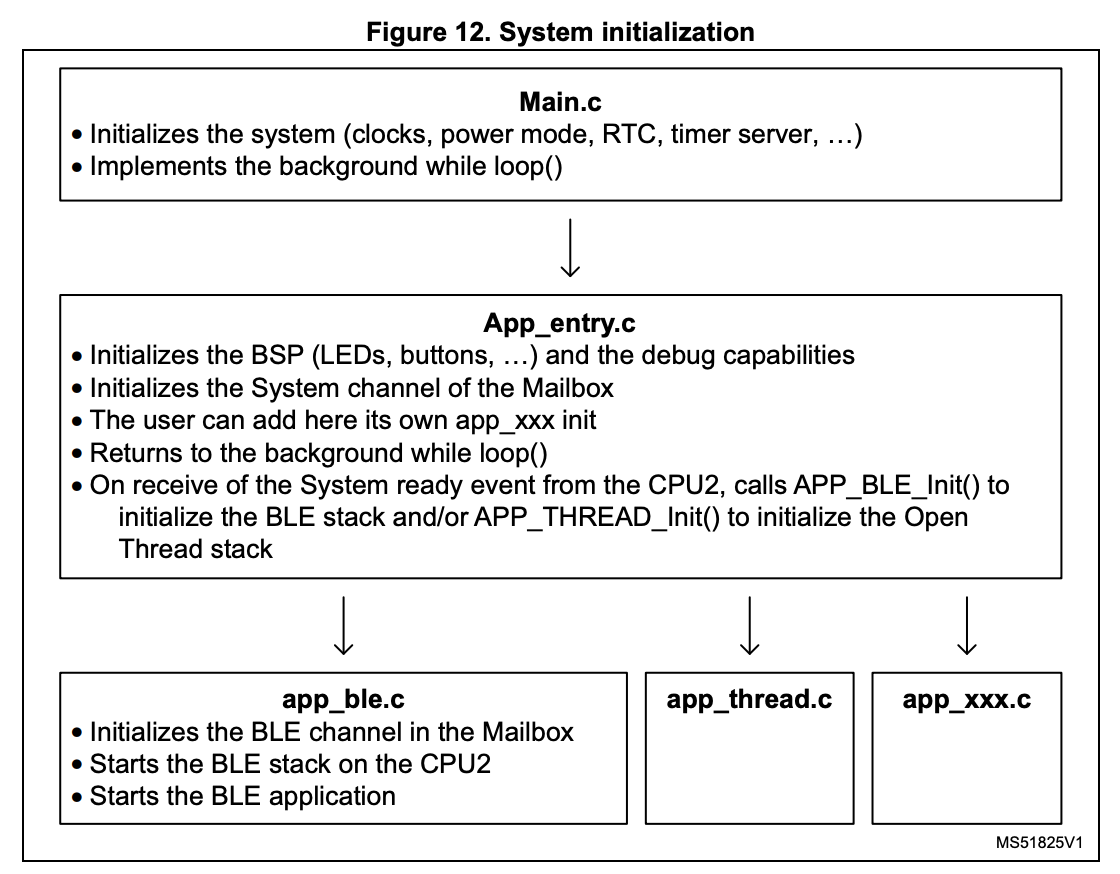
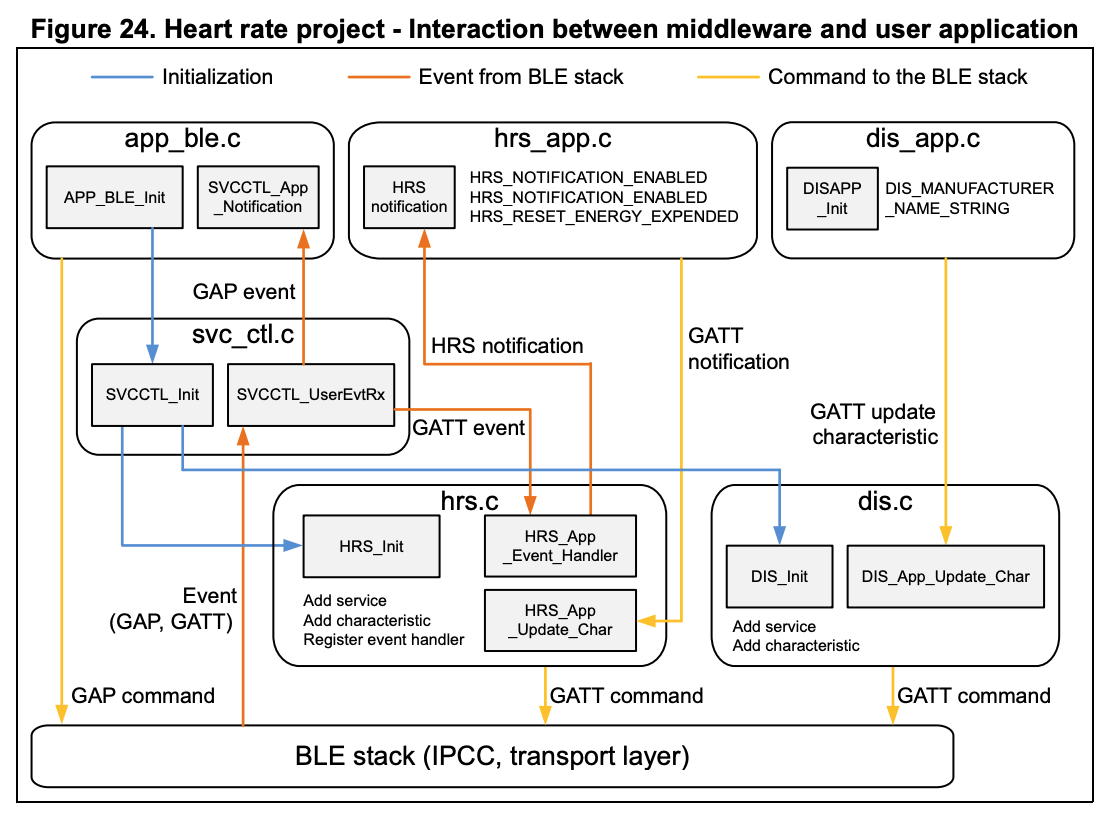
Below is the structure as elaborated in the Application Note AN5289. The structure is not the simplest, so it's worth spending a little time poking around and getting familiar:
The Example Services
DTM is a Direct Test Mode example in line with bluetooth spec– it ignores CPU1 and simply passes through UART commands from the UART peripheral. This is great for hooking it up to the computer and making sure the RF circuitry works, but it's not great for us since it doesn't expose an interface for applications running on CPU1.
The HR example is nice because it notifies the master, but it is quite complex as we've seen, and it's intended for HR data. This could be adapted for a service that requires the notifiction structure with a fair amount of work. It implements the Bluetooth Spec defined HR Service.
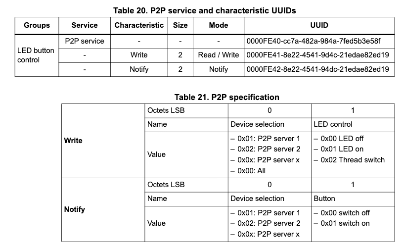
STM offers two proprietary services: the P2P Service and the FUOTA Service (Flash Update Over-The-Air). The example we will actually use for everything we're going to do is the P2P service, which features two way communication between devices or a device and a smartphone application. One characteristic of the service features a R/W value (polled and set by the central to interact with the LED); the other is a notification characteristic (pushed by the peripheral to the device asynchronously when a button is pressed on the peripheral).
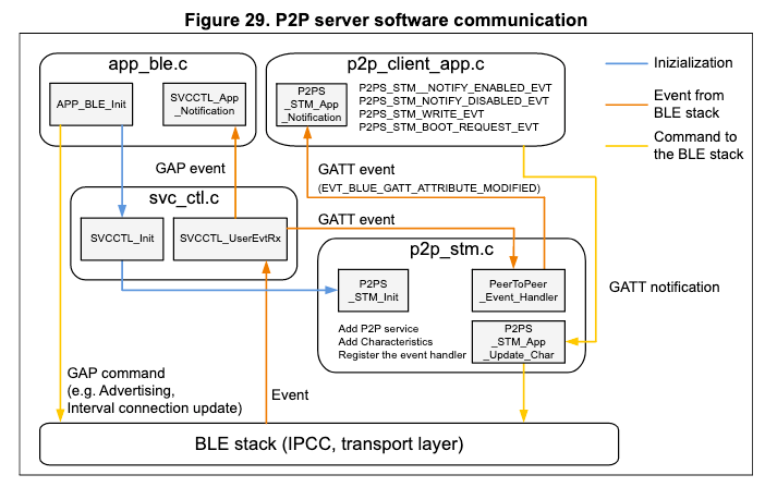
The P2P example advertises itself over GAP using a manufacturer specific packet. This is still using the ADV_IND packet as described in the GAP section above, but in addition to using industry standard AD_Types like Service UUID or Local Name, it appends a Manufacturer specific AD_Type (=0xFF):
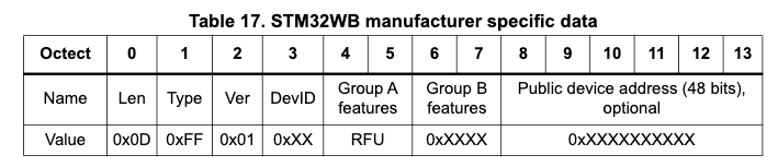
It is possible to set the device up as a router or in FUOTA mode, but we will care only about setting it up as a P2P server. For this, we expect values of DevID = 0x83 (CFG_DEV_ID_P2P_SERVER1). Group B Features are mostly reserved for future use (RFU) with the exception of turning on OTA reboot requess and Thread support, which we'll leave off (Group A and B should just be set to all zeros). The last six bytes are the optional BD_ADDR, which is redundant in the payload.
We create the packet payload by adding AdData (the section of repeating [Length | AD Type | AD Data]) using aci_gap_set_discoverable() for both the manufacturer specific data and a local_name, to identify our application.
For full details, I encourage you to read through the AN5289 manual pages 67-77 (Section 7.4).
Moving Towards Our Own Application
Let's start by loading in and testing the BLE_p2pServer example application, the same way we did the HR example. Import it into CubeMX, load/run it through the debugger onto our Nucleo board, and open the STM BLE example application to connect. You'll see that we can control the LED from the app; we can recieve a timestamped alarm when the button is pressed; we can also turn on cloud logging where we control the logging interval! This is a pretty nice general purpose example. Hopefully this should only take you a minute or two to get running at this point; if not, it's better to work out the kinks in your toolchain first.
Our Goals
Now we're going to use this P2P Server as a starting point for our own custom code. We'll make the following changes, familiarizing ourselves with the code in the process:
- 1. Change the human readable name of the device that is advertised
- 2. Use our React app to get notifications from the button
- 3. Use our React app to turn the LED on and off and query its state
- 4. Send a larger packet than a 0x00/0x01 from the peripheral to the central (a timestamp using the RTC, for instance)
- 5. Send a larger packet than a 0x00/0x01 from the central to the peripheral (a timestamp, for instance)
- 6. Log the incoming peripheral data and make sure it logs with the app in the background
- 7. Edit the Peripheral to store data that isn't recieved/when notifications are off and retransmit it when the Central bonds again
Change the Advertising Name
First let's edit the human readable BLE advertised name. We go to STM32_WPAN/App/app_ble.c, and in line 240 we see the start of the advertising data construction.
#if (P2P_SERVER1 != 0)
static const char local_name[] = { AD_TYPE_COMPLETE_LOCAL_NAME ,'P','2','P','S','R','V','1'};
uint8_t manuf_data[14] = {
    sizeof(manuf_data)-1, AD_TYPE_MANUFACTURER_SPECIFIC_DATA,
    0x01/*SKD version */,
    CFG_DEV_ID_P2P_SERVER1 /* STM32WB - P2P Server 1*/,
    0x00 /* GROUP A Feature  */,
    0x00 /* GROUP A Feature */,
    0x00 /* GROUP B Feature */,
    0x00 /* GROUP B Feature */,
    0x00, /* BLE MAC start -MSB */
    0x00,
    0x00,
    0x00,
    0x00,
    0x00, /* BLE MAC stop */
};
#endif
This is true for the various enumerated P2P_SERVERs on the following lines as well. We can change the local name in this static const char local_name.
We also can change it in line 863:
if (role > 0)
  {
    const char *name = "P2PSRV1";
   ...
The first instance of these is the 'local_name'; the second instance is the 'name'. These are advertised as two separate fields, but it's best practice for our applications just to make them the same thing.
A word of caution: I thought this hadn't worked when I updated it, for a while. You might need to restart/repower the Nucleo AND whatever device you're using to look at BLE; these names can be cached opaquely at a low level. They really aren't supposed to change. If they don't update, reset everything, turn on/off bluetooth, move on, and come back to it later.
Read and Write the Button State in React
We can use the exact same code as for the HR example here, changing the name of the device we want to connect to in the scanAndConnect function (to whatever we set it to above). It will connect and register for the notifications of the button pressing! We can add a little code that will print things conditionally on the button press in our BLE render function, like so:
{this.state.values['0000fe42-8e22-4541-9d4c-21edae82ed19']=='0101'
            ?
            <Text> Button Pushed
            </Text>
            :
            <Text> Button NOT Pushed
            </Text>
}
The UUID is set for this notification of the button given the spec in AN5289 (the notify characteristic).
The above code will show 'Button Pushed' or 'Button NOT Pushed' in your React app, toggled by the actual button press!
Read and Write the LED State in React
Now let's connect and control the LED. We can also see in our debugger that we have a characterstic with UUID '0000fe41-8e22-4541-9d4c-21edae82ed19' (as expected) that has isReadable==True and isWritableWithoutResponse==True.
We can see there are three options for writing a value to a characteristic without a response (https://github.com/Polidea/react-native-ble-plx/wiki/Characteristic-Writing)– each one uses an ble object at a different level of abstraction, and requires the missing information passed (blemanager object, the device object, and the characteristic itself). We'll just register our characteristic and use characteristic.writeWithoutResponse(valueBase64).
First we modify our constructor so our state has writeCharacteristic and ledState field:
this.state = {info: "", values: {}, writeCharacteristic: null, ledState: false}
Now we'll modify our loop that runs through the the device characteristics to append the write characteristic we expect:
if (c[i].isWritableWithoutResponse){
    console.log('saving characteristic that is writable!!')
    this.setState({writeCharacteristic: c[i]})
}
Next, we'll make a write function that toggles the LED given our LEDState (we'll also need functions to convert a common sense hex value to base64 (adapted from https://stackoverflow.com/questions/23190056/hex-to-base64-converter-for-javascript):
  hexToBase64(str) {
    return btoa(str.match(/\w{2}/g).map(function(a) {
        return String.fromCharCode(parseInt(a, 16));
    }).join(""));
  }

  toggleLED(){
    console.log('toggle LED function called!')
    var newLedVal = !this.state.ledState
    if  (this.state.writeCharacteristic){
        if (newLedVal){
        this.state.writeCharacteristic.writeWithoutResponse(this.hexToBase64('0101'))
        console.log('wrote ' + this.hexToBase64('0101'))
        }
        else {
        this.state.writeCharacteristic.writeWithoutResponse(this.hexToBase64('0100'))
        console.log('wrote ' + this.hexToBase64('0100'))
        }
        this.setState({ledState: newLedVal})
    }
  }
Finally we need a button to call this toggleLED function in the renderer:
<TouchableHighlight style={{borderColor: this.state.ledState ? 'green' : 'red', borderWidth: 4, borderRadius: 10, height:30, width:100, justifyContent:'center', alignItems:'center'}} onPress={this.toggleLED.bind(this)}>
     <Text>LED IS {this.state.ledState ? 'on' : 'off'}</Text>
</TouchableHighlight>
And that's all there is to it! We now have a React app with a small button that tracks the LED state and toggles it on and off.
Send More Information
We're gonna bump up our data from 8 bits; for me, the target is really timestamped 16 bit values (RTC timestamps are 64 bits, so >10 bytes). The default configuration should work up to 20 bytes; if we need more, we need to edit the MTU size ( CFG_BLE_MAX_ATT_MTU in app_conf and potentially renegotiate the connection using aci_gatt_exchange_config and hci_le_set_data_length), but for our purposes we'll stick within the 20 byte size. Here we'll send 16 bytes.
First, let's take a look at the existing code for sending our current notification. It exists across a few different files:
 //from p2p_server_app.c
 P2PS_Send_Notification(void) {

   P2PS_STM_App_Update_Char(
     P2P_NOTIFY_CHAR_UUID,
     (uint8_t *)&P2P_Server_App_Context.ButtonControl
   );

 }

//from p2p_stm.c  CALLS:

P2PS_STM_App_Update_Char(uint16_t UUID, uint8_t *pPayload)  {

  aci_gatt_update_char_value(
    aPeerToPeerContext.PeerToPeerSvcHdle,
    aPeerToPeerContext.P2PNotifyServerToClientCharHdle,
    0, /* charValOffset */
    2, /* charValueLen */
    (uint8_t *)  pPayload
  );
}

 //from ble_gatt_aci.c  CALLS:

 aci_gatt_update_char_value(uint16_t Service_Handle,
                                      uint16_t Char_Handle,
                                      uint8_t Val_Offset,
                                      uint8_t Char_Value_Length,
                                      uint8_t Char_Value[])
The last of these is updating a characteristic that is already registered with a certain packet size:
//from p2p_stm.c (that third line is the packet byte size

aci_gatt_add_char(aPeerToPeerContext.PeerToPeerSvcHdle,
                      UUID_TYPE_128, &uuid16,
                      2,
                      CHAR_PROP_NOTIFY,
                      ATTR_PERMISSION_NONE,
                      GATT_NOTIFY_ATTRIBUTE_WRITE, /* gattEvtMask */
                      10, /* encryKeySize */
                      1, /* isVariable: 1 */
                      &(aPeerToPeerContext.P2PNotifyServerToClientCharHdle));


//from ble_gatt_aci.c  CALLS:

tBleStatus aci_gatt_add_char(uint16_t Service_Handle,
                             uint8_t Char_UUID_Type,
                             Char_UUID_t *Char_UUID,
                             uint16_t Char_Value_Length,
                             uint8_t Char_Properties,
                             uint8_t Security_Permissions,
                             uint8_t GATT_Evt_Mask,
                             uint8_t Enc_Key_Size,
                             uint8_t Is_Variable,
                             uint16_t *Char_Handle)
First let's make a version of P2P_STM_App_Update_Char that accepts something other than a 2 byte char. In p2p_stm.c:
tBleStatus P2PS_STM_App_Update_Int16(uint16_t UUID, uint16_t *pPayload, uint8_t num_words)
{
  tBleStatus result = BLE_STATUS_INVALID_PARAMS;
  switch(UUID)
  {
    case P2P_NOTIFY_CHAR_UUID:

     result = aci_gatt_update_char_value(aPeerToPeerContext.PeerToPeerSvcHdle,
                             aPeerToPeerContext.P2PNotifyServerToClientCharHdle,
                              0, /* charValOffset */
                             2*num_words, /* charValueLen */
                             (uint8_t *)  pPayload);

      break;

    default:
      break;
  }

  return result;
}
And we need to declare our new function in the appropriate header:
//STM32CubeWB/Middlewares/ST/STM32_WPAN/ble/svc/Inc/p2p_stm.h

...
//add this line
tBleStatus P2PS_STM_App_Update_Int16(uint16_t UUID,  uint16_t *pPayload, uint8_t num_words);
And of course we need to edit the original declaration of the characteristic so it's set up to recieve 16 bytes in p2p_stm.c. We simply have to change the Char_Value_Length from 2 to 16.
Now let's edit our button push in P2PS_Send_Notification from p2p_server_app.c to try and send a larger packet:
...

const uint16_t test_data[8] = {0x0123, 0x4567, 0x89AB, 0xCDEF, 0x0A0A, 0x1B1B, 0x2C2C, 0x3D3D};

if(P2P_Server_App_Context.Notification_Status){
  ...
  //comment out our old command to send ButtonControl Byte
  //P2PS_STM_App_Update_Char(P2P_NOTIFY_CHAR_UUID, (uint8_t *)&P2P_Server_App_Context.ButtonControl);

  //call our new function
  P2PS_STM_App_Update_Int32(P2P_NOTIFY_CHAR_UUID, test_data, 8);
With the above code, we'll see in our React App that pushing the button sends all the data; however the byte order is reversed ( 0x2301, 0x6745, 0xAB89, 0xEFCD, ...). However, if we use the same function and send an array of bytes instead of words, the correct order is preserved:
//same test data as above, but as bytes
const uint8_t test_data[16] = {0x01, 0x23, 0x45, 0x67, 0x89, 0xAB, 0xCD, 0xEF, 0x0A, 0x0A, 0x1B, 0x1B, 0x2C, 0x2C, 0x3D, 0x3D};

//cast it to (uint16_t *) so it will work with our previous function
P2PS_STM_App_Update_Int16(P2P_NOTIFY_CHAR_UUID, (uint16_t *)&test_data, 8);
We'll have to be careful when working with words on the STM32 so that the byte order is not reversed.
We also notice that we can send less data than the maximum specified packet size using this technique, without modification:
//same test data as above, but half as much
const uint8_t test_data[8] = {0x01, 0x23, 0x45, 0x67, 0x89, 0xAB, 0xCD, 0xEF};

//cut the passed number of words in half, though the characteristic is the same and supports the full 16 bytes
P2PS_STM_App_Update_Int16(P2P_NOTIFY_CHAR_UUID, (uint16_t *)&test_data, 4);
So Finally, we'll finish our edits here in a way that we can easily pass byte or word arrays:
//IN p2p_stm.c

//SET aci_gatt_add_char length to *20*; that way we can send up to 20 bytes in each message

//ADD the following two functions:

tBleStatus P2PS_STM_App_Update_Int16(uint16_t UUID, uint16_t *pPayload, uint8_t num_words)
{

  uint16_t byte_reversed[num_words];

  for (uint8_t i = 0; i < num_words; i++){
	byte_reversed[i] = (pPayload[i] & 0xFF00) >> 8 | (pPayload[i] & 0x00FF) << 8;
  }

  tBleStatus result = BLE_STATUS_INVALID_PARAMS;
  switch(UUID)
  {
    case P2P_NOTIFY_CHAR_UUID:

     result = aci_gatt_update_char_value(aPeerToPeerContext.PeerToPeerSvcHdle,
                             aPeerToPeerContext.P2PNotifyServerToClientCharHdle,
                             0, /* charValOffset */
                             2*num_words, /* charValueLen */
                             (uint8_t *)  byte_reversed);

      break;

    default:
      break;
  }

  return result;
}

tBleStatus P2PS_STM_App_Update_Int8(uint16_t UUID, uint8_t *pPayload, uint8_t num_bytes)
{
  tBleStatus result = BLE_STATUS_INVALID_PARAMS;
  switch(UUID)
  {
    case P2P_NOTIFY_CHAR_UUID:

     result = aci_gatt_update_char_value(aPeerToPeerContext.PeerToPeerSvcHdle,
                             aPeerToPeerContext.P2PNotifyServerToClientCharHdle,
                             0, /* charValOffset */
                             num_bytes, /* charValueLen */
                             (uint8_t *)  pPayload);

      break;

    default:
      break;
  }

  return result;
}


//IN p2p_stm.h

//ADD the function handles:

tBleStatus P2PS_STM_App_Update_Int16(uint16_t UUID,  uint16_t *pPayload, uint8_t num_words);
tBleStatus P2PS_STM_App_Update_Int8(uint16_t UUID, uint8_t *pPayload, uint8_t num_bytes);


//now we can call this on byte arrays and word arrays up to 20 bytes long, and the byte order will be preserved correctly when we send.
Sending more info to the STM
Within the p2p_server_app.c we find that all of the data we're sending back and forth is stored in P2P_Server_App_Context, which is a nice abstraction to help us keep data organized.
First let's add a uint64_t OTATimestamp, a uint8_t OTA12HrFormat, and a uint8_t OTADaylightSavings to the P2P_Server_App_Context struct declaration in p2p_server_app.c. We're going to send a timestamp value over BLE from our React App.
Now we need to edit the payload handler to deal with our new timestamp value. In the same file, we see P2PS_STM_App_Notification is the function that deals with incoming data. We'll add one memcpy to push our timestamp value to the OTATimestamp field of the P2P_Server_App_Context struct.
#if(P2P_SERVER1 != 0)
      if(pNotification->DataTransfered.pPayload[0] == 0x01){ /* end device 1 selected - may be necessary as LB Routeur informs all connection */

    	memcpy(&P2P_Server_App_Context.OTATimestamp, &(pNotification->DataTransfered.pPayload[2]), 8);
        P2P_Server_App_Context.OTA12HrFormat = pNotification->DataTransfered.pPayload[10];
    	P2P_Server_App_Context.OTADaylightSavings = pNotification->DataTransfered.pPayload[11];


    	if(pNotification->DataTransfered.pPayload[1] == 0x01)
        {
          BSP_LED_On(LED_BLUE);
          APP_DBG_MSG("-- P2P APPLICATION SERVER 1 : LED1 ON\n");
          APP_DBG_MSG(" \n\r");
          P2P_Server_App_Context.LedControl.Led1=0x01; /* LED1 ON */
        }
        if(pNotification->DataTransfered.pPayload[1] == 0x00)
        {
          BSP_LED_Off(LED_BLUE);
          APP_DBG_MSG("-- P2P APPLICATION SERVER 1 : LED1 OFF\n");
          APP_DBG_MSG(" \n\r");
          P2P_Server_App_Context.LedControl.Led1=0x00; /* LED1 OFF */
        }
      }
#endif
We should alter our init code for this struct later on in the file as well to start the default values at 0x00:
void P2PS_APP_LED_BUTTON_context_Init(void){

  BSP_LED_Off(LED_BLUE);

  #if(P2P_SERVER1 != 0)
  P2P_Server_App_Context.LedControl.Device_Led_Selection=0x01; /* Device1 */
  P2P_Server_App_Context.LedControl.Led1=0x00; /* led OFF */
  P2P_Server_App_Context.OTATimestamp=0x0000000000000000;
  P2P_Server_App_Context.OTA12HrFormat=0x00;
  P2P_Server_App_Context.OTADaylightSavings=0x00;
  P2P_Server_App_Context.ButtonControl.Device_Button_Selection=0x01;/* Device1 */
  P2P_Server_App_Context.ButtonControl.ButtonStatus=0x00;
#endif
We'll also send that data back on a button press; where we had modified our P2P_Send_Notification function to send random test data, let's edit it to send the 64 bit timestamp value instead:
void P2PS_Send_Notification(void)
{

  if(P2P_Server_App_Context.ButtonControl.ButtonStatus == 0x00){
    P2P_Server_App_Context.ButtonControl.ButtonStatus=0x01;
  } else {
    P2P_Server_App_Context.ButtonControl.ButtonStatus=0x00;
  }

  if(P2P_Server_App_Context.Notification_Status){
    APP_DBG_MSG("-- P2P APPLICATION SERVER  : INFORM CLIENT BUTTON 1 PUSHED \n ");
    APP_DBG_MSG(" \n\r");

    P2PS_STM_App_Update_Int8(P2P_NOTIFY_CHAR_UUID, (uint8_t *)&P2P_Server_App_Context.OTATimestamp, 8);


   } else {
    APP_DBG_MSG("-- P2P APPLICATION SERVER : CAN'T INFORM CLIENT -  NOTIFICATION DISABLED\n ");
   }

  return;
}
Just like in the case for the STM writing more than 2 bytes, we need to change the max size when we register our characteristic using aci_gatt_add_char , as well as our aci_gatt_update_char_value in p2p_stm.c (here we again make it up to 20 bytes, here we have to update it in two places):
 /**
     *  Add LED Characteristic
     */
    COPY_P2P_WRITE_CHAR_UUID(uuid16.Char_UUID_128);
    aci_gatt_add_char(aPeerToPeerContext.PeerToPeerSvcHdle,
                      UUID_TYPE_128, &uuid16,
                      20,
                      CHAR_PROP_WRITE_WITHOUT_RESP|CHAR_PROP_READ,
                      ATTR_PERMISSION_NONE,
                      GATT_NOTIFY_ATTRIBUTE_WRITE, /* gattEvtMask */
                      10, /* encryKeySize */
                      1, /* isVariable */
                      &(aPeerToPeerContext.P2PWriteClientToServerCharHdle));


...


tBleStatus P2PS_STM_App_Update_Char(uint16_t UUID, uint8_t *pPayload)
{
  tBleStatus result = BLE_STATUS_INVALID_PARAMS;
  switch(UUID)
  {
    case P2P_NOTIFY_CHAR_UUID:

     result = aci_gatt_update_char_value(aPeerToPeerContext.PeerToPeerSvcHdle,
                             aPeerToPeerContext.P2PNotifyServerToClientCharHdle,
                              0, /* charValOffset */
                             20, /* charValueLen */
                             (uint8_t *)  pPayload);

      break;

    default:
      break;
  }

  return result;
}/* end P2PS_STM_Init() */
NOTE: the GATT will cache aspects of the service, including the packet size. There is a Service Changed Characteristic for when you're doing this on the fly, but in our cases it actually probably makes sense to just be aware that updates might require a restart of various devices to populate.
EXTRA NOTE: IF YOU ARE HAVING ISSUES WITH HOT-RELOADING OF YOUR JAVASCRIPT CODE, GO TO THE NETWORK TAB IN THE BROWSER INSPECTION TOOLS AND MAKE SURE 'DISABLE CACHE' IS CHECKED!!!!
Let's grab a javascript date and put it in BCD format (in which a month like December, month 12, is coded as 0x12– we use hex bytes to represent the decimal values). Here's some code I wrote to generate a timestamp object we can then work with on the STM32:
//at the very top of the javascript file:

Date.prototype.stdTimezoneOffset = function () {
  var jan = new Date(this.getFullYear(), 0, 1);
  var jul = new Date(this.getFullYear(), 6, 1);
  return Math.max(jan.getTimezoneOffset(), jul.getTimezoneOffset());
}

Date.prototype.isDstObserved = function () {
    return this.getTimezoneOffset() < this.stdTimezoneOffset();
}


//as a member function:

getDateInBCD(format12 = true) {
    //returns DAY (1byte) MONTH (1byte) DATE (1byte) YEAR (1byte) HR (1byte)
    //MIN (1byte) SEC (1byte) 12HRFORMAT (1byte, 00=24HR) AMorPM (1byte, 00=AM)
    //DAYLIGHTSAVINGS (1byte, 00=None 01=Add1hr)
    //all as a string

    console.log('Constructing Date...')
    //BCD means we use 0x01-0x12, skipping 0x0A-0x0F (hex *reads* right)
    var day = ("0" + new Date().getDay()).slice(-2);          //uint8_t 0x01-0x07, Mon-Sun
    var month = ("0" + (new Date().getMonth() + 1)).slice(-2);  //uint8_t 0x01-0x12
    var date = ("0" + new Date().getDate()).slice(-2);        //uint8_t 0x01-0x31
    var year = String(new Date().getFullYear()).slice(-2);    //uint8_t 0x20

    var hour = new Date().getHours();    //uint8_t Hours 0x00-0x023 if RTC_HourFormat_24, 0x00 to 0x12 if RTC_HourFormat_12
    var min  = ("0" + new Date().getMinutes()).slice(-2); //uint8_t Min 0x00 to 0x59
    var sec  = ("0" + new Date().getSeconds()).slice(-2); //uint8_t Sec 0x00 to 0x59

    //uint8_t TimeFormat to 0x00 for FORMAT12_AM, 0x40 for FORMAT12_PM
    var formatAM = hour >= 12 ? 1 : 0;
    if (format12) { hour = hour % 12; hour = hour ? hour : 12;}
    hour = ("0" + hour).slice(-2);

    //uint32_t DayLightSavings; use RTC_DAYLIGHTSAVINGS_SUB1H, RTC_DAYLIGHTSAVINGS_ADD1H, or RTC_DAYLIGHTSAVING_NONE
    var daylight = new Date().isDstObserved() ? 1 : 0; // if 1, ADD1H; else NONE

        return day + month + date + year + hour + min + sec  + '0' + formatAM  + '0' + (format12 ? 1 :0) + '0' + daylight;


  }


//now we edit our button toggle to send this info as well:

...
if  (this.state.writeCharacteristic){
 if (newLedVal){

var timestamp_string = this.getDateInBCD()
          this.state.writeCharacteristic.writeWithoutResponse(this.hexToBase64('0101' + timestamp_string))

console.log('wrote 0x0101' + timestamp_string + ' == ' + this.hexToBase64('0101' + timestamp_string))

}
...
This sends 10 bytes – the first 8 will fit into our OTAtimestamp and include DAY:MONTH:DATE:YEAR:HOUR:MIN:SEC:AMPM. The last 2 bytes are format bytes which indicate whether it is in 24 or 12 hour format, and whether it is currently daylight savings or not and can be saved as two uint8_t vals.
All of this should give us a round trip where we can easily see our timestamp, generated from our app, sent to and stored on the STM32, and then sent back!
A Note on Endianness
Both systems are Little Endian, but BLE communication works in a Big Endian fashion. To fix this, we need to reverse the bytes when sending/receiving, which I've chosen to do only on the javascript side of things. I've made the following changes to ensure my packets follow the right order:
reverseBytes(str){
  //bytes are 2 chars long
  //both systems are Little Endian; transport protocol is Big Endian
  //thus, data always gets flipped in transit

 s = str.replace(/^(.(..)*)$/, "0$1"); // add a leading zero if needed
 var a = s.match(/../g);             // split number in groups of two
 a.reverse();                        // reverse the groups
 return a.join("");                 // join the groups back together
}

...

  updateValue(key, value) {
    hexval = this.reverseBytes(this.base64ToHex(value));
    console.log('update ' + key + ' : ' + hexval)
    this.setState({values: {...this.state.values, [key]: hexval}})
  }

...

var timestamp_string = this.getDateInBCD()
this.state.writeCharacteristic.writeWithoutResponse(this.hexToBase64(this.reverseBytes('0101' + timestamp_string)))
console.log('wrote 0x0101' + timestamp_string + ' == ' + this.hexToBase64('0101' + timestamp_string))
Stay tuned for more posts exploring the link between STM32 and React-Native over BLE!
See https://github.com/dramsay9/react-stm32-bluetooth-example for the working code.
Quick Reference
For react, open workspace file. Run on phone, open http://localhost:8081/debugger-ui/. Make sure it's connected to the same wifi as your phone.
'Device not found on target' means hold down the reset button on the nucleo, and let go after reaches 'waiting for debugger connection'.
'Could not locate device support files' means you need to download the right files from here: https://github.com/iGhibli/iOS-DeviceSupport/tree/master/DeviceSupport and then
Then, go to Applications -> Xcode. Right click and open Show Package Contents. Then, paste to Contents -> Developer -> Platforms -> iPhoneOS.platform -> DeviceSupport and restart Xcode. (from https://stackoverflow.com/questions/39655178/xcode-could-not-locate-device-support-files)
Background capabilities requires restoreStateIdentifier and restoreStateFunction passed to BLEManager.